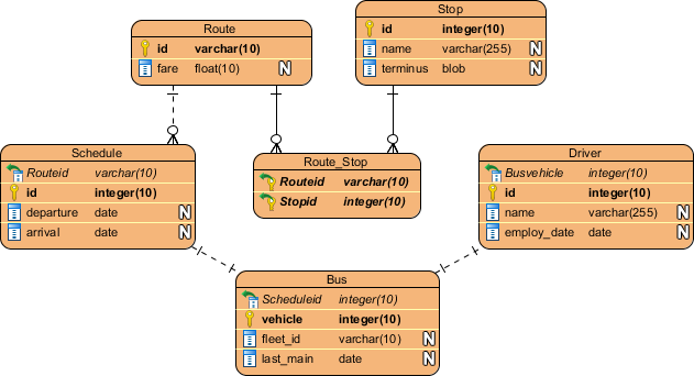
- Create a new project by selecting Project > New from the application toolbar. In the New Project window, enter Bus Route Management as project name and click Create Blank Project.
- To create an ERD, select Diagram > New from the toolbar. In the New Diagram window, select Entity Relationship Diagram and click Next. Enter Bus Route Management as diagram name and click OK.
- Let's start by creating the first entity Route. Select Entity in diagram toolbar and click on the diagram to create an entity. Name the entity Route and press Enter to confirm.

- Create columns in Route. Let's start with a primary key. Right-click on entity Route and select New Column from popup menu.
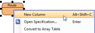
- Enter +id : varchar(10) and press Enter. Note that the + sign means that the column is a primary key. Varchar is the column type and 10 is the length.

- Enter fare : float and press Enter, then Esc to create another column.

- Create entity Stop. A bus route has many bus stops, while a stop can be shared by many routes. Therefore, there is a many-to-many relationship between Route and Stop. Place the mouse pointer over the Route entity. Drag out the Resource Catalog icon at top right.

-
Release the mouse button and select Many-to-Many Relationship -> Entity from Resource Catalog.
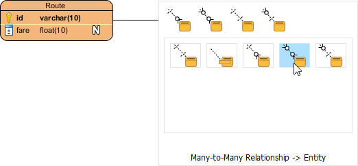
Name the new entity Stop, You can see that a linked entity Route_Stop is automatically created in between Route and Stop, with foreign key added.
-
Create the following columns in Stop:
Key Name Type PK id int(10) name varchar(255) terminus blob
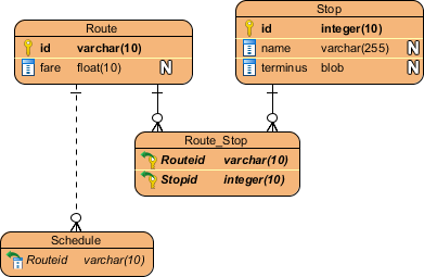
The diagram should now become: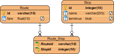
- A route has multiple bus schedules. Create an entity Schedule from Route with a one-to-many relationship. Move the mouse pointer to Route. Press and drag out the Resource Catalog icon. Select One-to-Many Relationship -> Entity to create entity Schedule.
-
Create the following columns in Schedule:
Key Name Type PK id int(10) departure date arrive date -
A schedule is handled by a bus. Create an entity Bus from Schedule, with an one-to-one relationship. Create the following columns in Bus:
Key Name Type PK vehicle_id int(10) fleet_id varchar(10) last_main date
The diagram should become: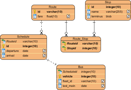
-
A bus is driven by a bus driver. Create entity Driver from Bus with a one-to-one relationship. Add the following columns to Driver:
Key Name Type PK id int(10) name varchar(255) employ_date date
This is the final ERD.